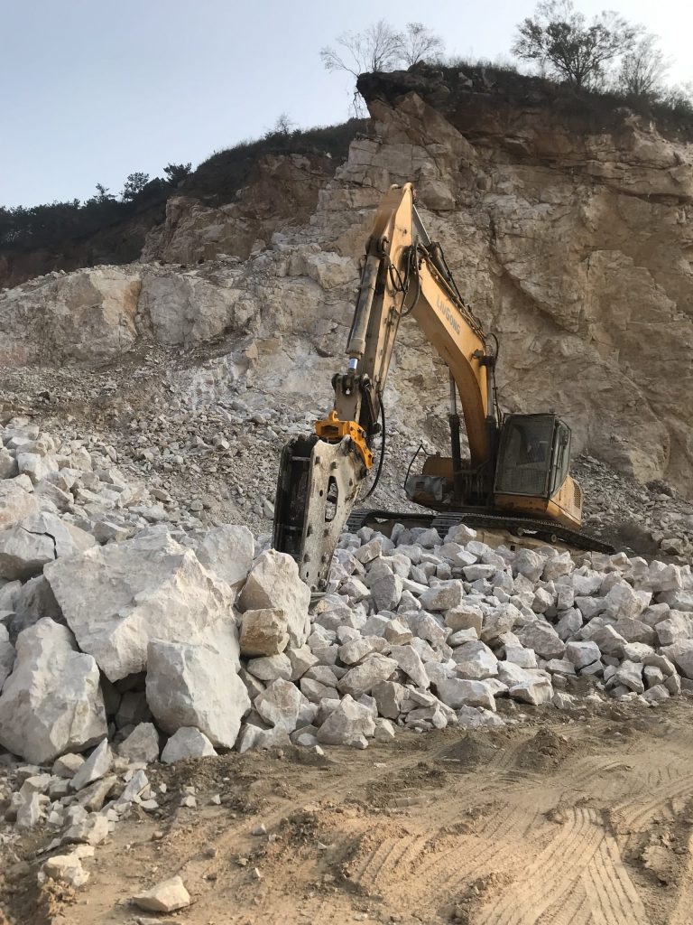
Excavator hydraulic breakers are usually used to break rock, concrete, asphalt and other construction and aggregate materials. However, Wear and tear is an outright certainty, so maintaining the breaker is vital to keeping it running at peak efficiency.
precautions during use of hydraulic Breaker
Before Operation
- Check the oil level in the tank
- Grease up Chisel
- Check bolts of looseness
- Charge Nitrogen (N2) Gas in Back Head and Accumulator to meet standard pressure required
During Operation
- Avoid blank hitting
- Must place chisel vertically to surface
- Do not blow more than one minute on same spot
- Must replace new front cover once the gap between front cover and chisel is over the maximum wear allowance
- Do not operate the breaker when the cylinder on the excavator is fully extended.
Storage
- When dismounting breaker, be sure to put plugs in
- Foreign matters in piping will be the cause of trouble
- Discharging Nitrogen (N2)
- Be sure to keep piston in the position of back head side
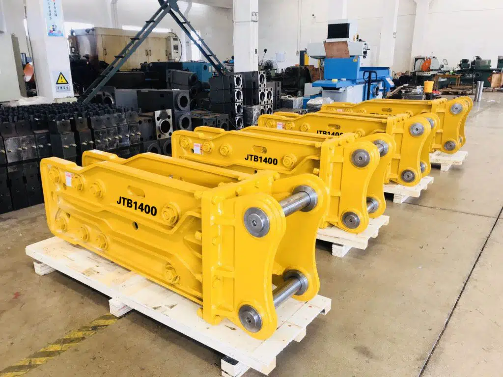
Moving and Lifting Breaker
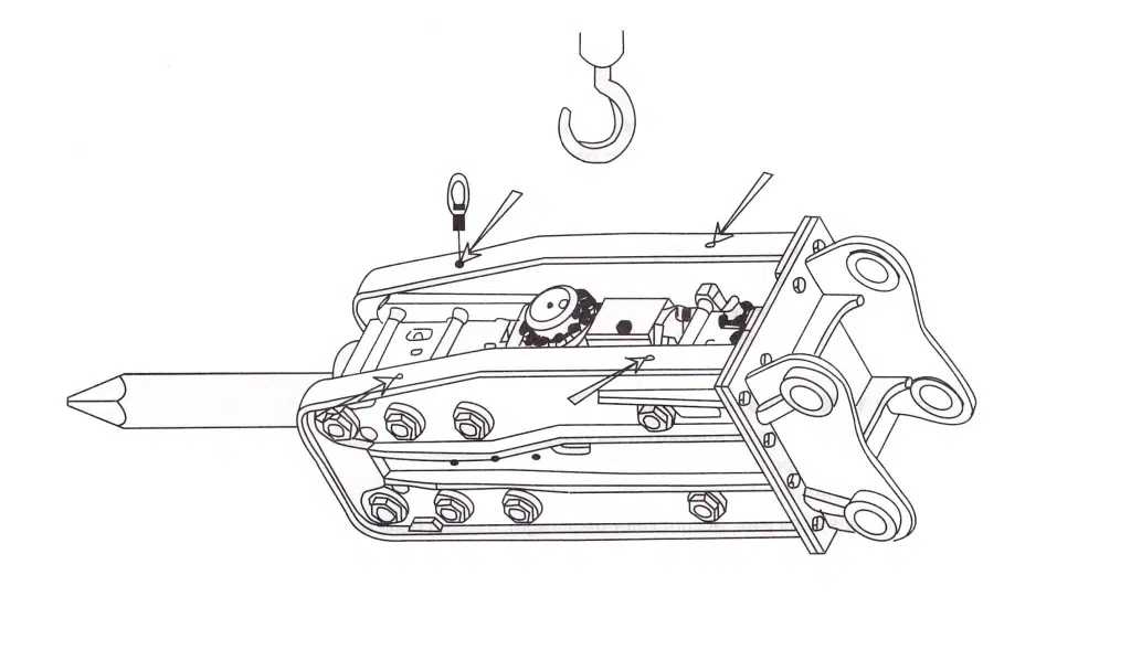
- Always use eye-bolts when lifting & moving the hydraulic breaker, after fasten up to bracket.
- Fasten the ropes to the shackles (four pieces) and lift the hydraulic breaker up
- Remove the eye-bolts before hydraulic breaker operation
| Model | Eye bolt size (mm) | Wire Rope Size (mm) |
| 135/140/150/155/165 | M24 | ∮16 |
| 175 | M30 | ∮20 |
Maintenance intervals
Before hydraulic breaker operation, be sure to check the following points.
Every 3 hours
- Apply the grease to the front head.
- Check hydraulic oil temperature, piping and hose connections, and working conditions.
- Check the tightness of fasteners.
Every 10 hours, or Daily
- If rough skin on the total and tool pins have been found, it must be removed.
- Check the nitrogen gas pressure in back head.
- Retighten the bracket bolts.
Every 50 hours, or Weekly
- Check the clearance between tool and front cover.
- Check hydraulic hoses.
- Retighten the through bolts.
Every 1000 hours, or Six (6) months
- Factory inspection by authorized service personal recommended.
- All hydraulic pipe and hose connections.
- Hose interference from carrier movement.
- Conditions of oil filter, accumulator diaphragm, through bolts and tool pins.
Every 2000 hours, or Annually
- All hydraulic pipe and hose connections.
- Hose interference with excavator boom.
- Conditions of oil filter, accumulator diaphragm, through bolts and tool pins.
- All seals.
- Conditions of piston, front cover, inner bush.
Hydraulic oil standard
Normally, any hydraulic oil originally intended for base machine can be used in the hydraulic breaker. However, oil viscosity must be checked timely, because the oil may be heated much more in the hydraulic breaker works than in normal excavator works.
When hydraulic breaker is used continuously the oil temperature normalizes at certain levels, depending on conditions and carrier. At such temperatures, hydraulic oil viscosity should be 20-40 cST.
Recommended hydraulic oil
| Maker | ISO VG68(For hat weather use) | ISOVG46(For cold weather use) |
| ESSO | Nuto H68 | Univis N46 |
| SHELL | Tellus oil 68 | Tellus oil 46 |
| MOBILE | DTE 16 | DTE 15 |
| GULF | Harmony68 | Harmony 46 |
Usually, the hydraulic oil temperature of hydraulic breaker and base machine must be controlled between 40℃ and 60℃. When you operate the hydraulic breaker while the oil temperature exceeds 80℃, you must check the seals.
Replacement of hydraulic oil & filter
Contamination of hydraulic oil may result in part damage, not only in hydraulic breaker but also in carrier main components. We recommend hydraulic oil and oil filter replacement as shown in the following table, which is based on 100% hydraulic breaker operation.
| Hydraulic oil | First 250 hours Every 600 hours |
| Oil filters | First 50 hours Every 100 hours |
Hydraulic oil viscosity
The hydraulic breaker must not be started if hydraulic oil viscosity exceeds 1000 cST, not operated when hydraulic oil viscosity falls 15 cST.
Oil viscosity too high
- Start up difficulty
- Operation stiffness
- Irregular hydraulic breaker impact
- Danger of cavitation in pumps and hydraulic breaker.
- Valve sticking
- If the filter is very contaminated, hydraulic components could be damaged, due to open bypass valve.
Oil viscosity too low
- Efficiency losses from internal leakage.
- Damage to seals, O-rings.
- Accelerated wearing of parts, because of decreased lubrication efficiency
Cooling
Maximum permitted hydraulic oil temperature range in continuous hydraulic breaker use in 50-80 oC (120-175 oF), depending on viscosity of oil in the system. Therefore, a reliable hydraulic oil thermometer is necessary. If there is no thermometer on the carrier, one must be installed. Hydraulic oil temperature depends on ambient conditions, carrier cooling system efficiency, and on hydraulic breaker use.
When hydraulic breaker is used continuously, it is necessary to have a cooling system with extra cooling capacity, as compared with normal excavation work.
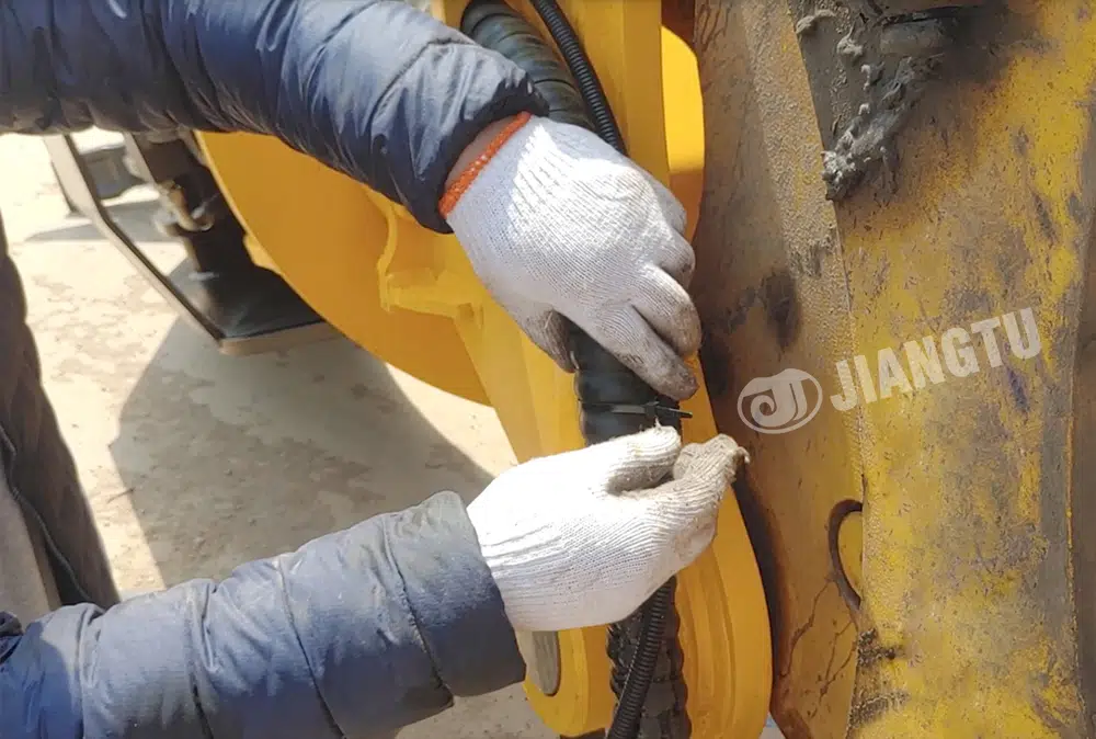
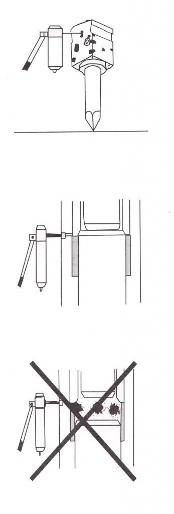
Apply Grease
Insufficient greasing may cause abnormal wear of front cover and tool, and tool breakage.Apply grease to grease nipple on front head every 3 hours. Adopt grease interval and amounts to tool wear rates and working conditions.
While greasing, hydraulic breaker must be upright against the tool, to ensure that grease will penetrate between tool and inner bush.
Recommended lubricant grease (NIGI NO.2)
| Maker | Grease |
| Esso | Beacon Q2 |
| Shell | Retinax AM |
| Mobile | Mobile Grease special |
Tool shank must be well lubricated before installed in front head.
Greasing label
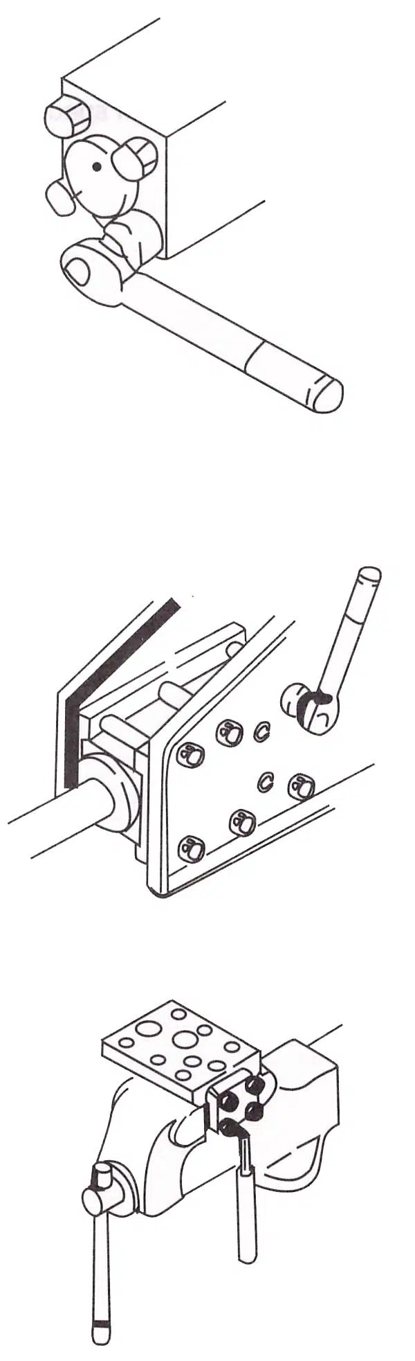
Inspection and Charging of Nitrogen (N2) gas
Back head
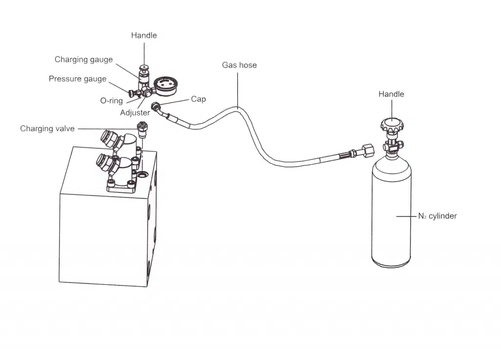
- Connect gas hose to N2 gas cylinder.
- Turn the handle of charging gauge counterclockwise before installing the charging gauge.
- Install charging gauge to charging valve. (Make sure that O-rings are installed on charging gauge.)
- Connect other end of gas hose to charging gauge.
- Slowly turn the handle of charging gauge clockwise to set charging pressure and turn handle of N2 gas cylinder clockwise.
- Turn the handle of charging gauge counterclockwise, and then turn the handle of N2 gas cylinder counterclockwise to close.
- Close the cap of charging gauge after gas hose is relieve from charging gauge.
- Recheck charging pressure in back head as turning the handle of charging gauge clockwise.
- Disconnect the gas hose from charging gauge.
- Install charging gauge on charging valve of back head completely.
- When turn the handle of charging gauge clockwise, gas pressure in back head is indicated on pressure gauge.
- If gas pressure is low, again perform operations (1) through (8), repeat until gas pressure rises to specified pressure.
- If gas pressure is excessive, slowly turn the adjuster of charging gauge counterclockwise, then gas pressure leaks from back head. When correct amount of gas pressure is shown, close the adjuster clockwise. When gas pressure is excessively high, breaker will not operate. Ensure that gas pressure is that specified pressure and O-ring in charging gauge is installed.
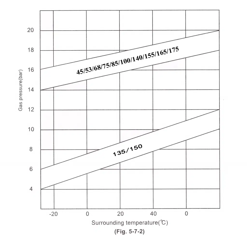
| Model | Charging Pressure (Kg/cm2) |
| 45 | 16-17 |
| 53 | 16-17 |
| 68 | 16-17 |
| 75 | 16-17 |
| 85 | 16-17 |
| 100 | 16-17 |
| 135 | 6-7 |
| 140(A) | 16-17 |
| 150 | 6-7 |
| 155 | 16-17 |
| 165 | 16-17 |
| 175 | 16-17 |
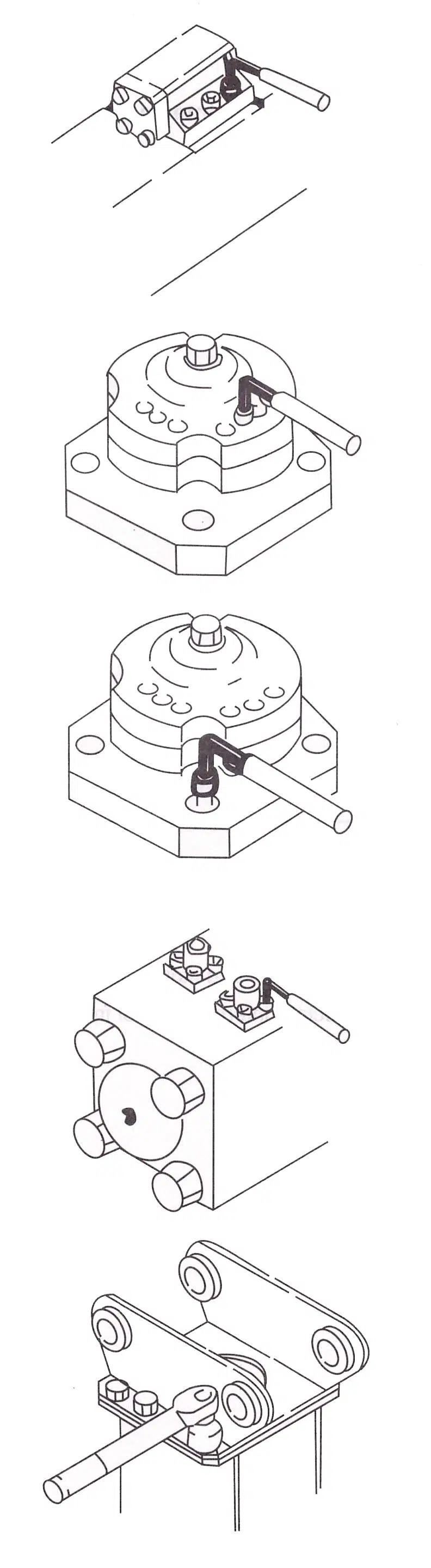
Accumulator
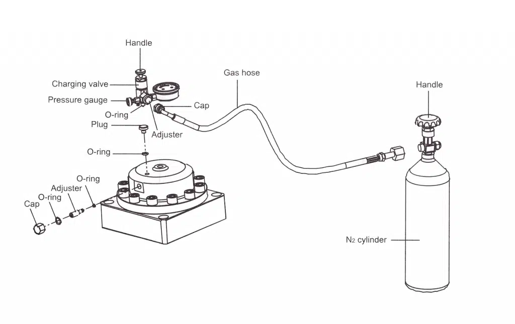
- Must be tightened the accumulator body and accumulator cover before charging the nitrogen gas in accumulator assembly.Use nitrogen gas only.
- The temperature of the hydraulic breaker main body must be normal when inspection or charging nitrogen gas of the accumulator.
- Be sure to use a charging gauge for charging the nitrogen gas.
- If the nitrogen gas is charged from gas cylinder without charging gauge, the diaphragm may damaged.
Inspection of charging pressure
- Turn the handle of charging gauge counterclockwise.
- Remove the A plug on the accumulator and charging gauge completely.
- Remove the cap of adjuster from accumulator.
- Turn the adjuster counterclockwise slowly to indicate accumulator charging pressure.
- Remove charging gauge and tighten plug an cap. (Ensure O-rings must be installed in plug and cap).
Charging accumulator with nitrogen gas.
- After performing steps same inspection of charging pressure.
- Connect gas hose charging gauge and N2 gas cylinder.
- Turn the adjuster counterclockwise after remove the cap from adjuster.
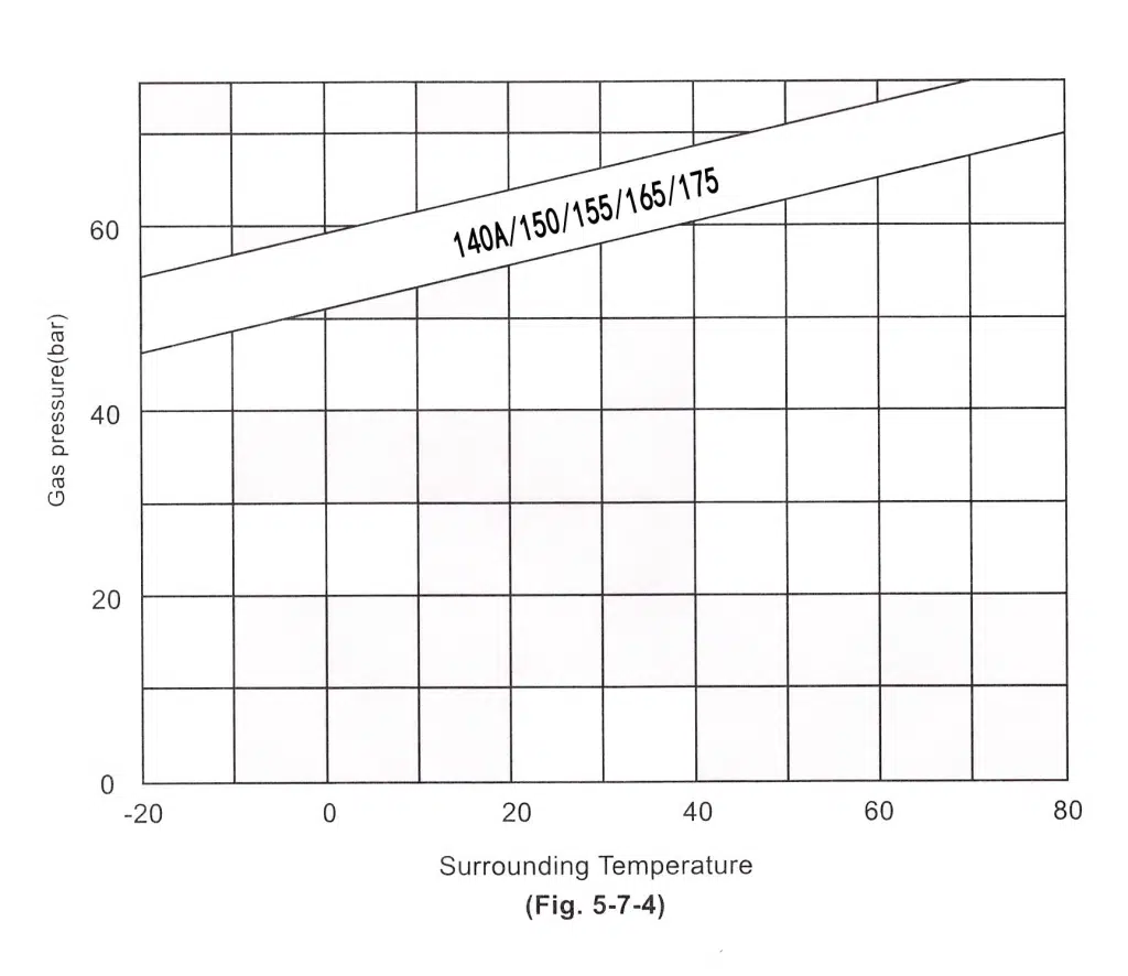
- Slowly turn handle of N2 gas counterclockwise to charge accumulator with N2 gas charging pressure.(refer in Fig.5-7-4)
- When accumulator is charged with N2 gas completely, close the adjuster fully.
- Turn the handle of N2 gas cylinder clockwise to close.
- Loosen adjuster of charging gauge to discharge N2 gas remaining in gas hose.
- Remove the gas hose from charging gauge to N2 gas cylinder.
- After removing gas hose, adjuster the pressure referring A) Inspection of charging pressure
- After charged accumulator with N2 gas, check gas leakage from adjuster, plug hole of accumulator.
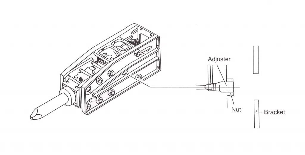
Pressure Setting
The pressure setting for hydraulic breaker must be lower than the base machine pressure setting in order to protect the pump of base machine.
Normally, set the pressure for hydraulic breaker about 5-10kg/cm2 lower than base machine pressure setting, when the main pressure of base machine is lower than below table.
If hydraulic breaker setting pressure higher than below table: That will be shorten durable of main pump and shorten service life of seals & tool in hydraulic breaker.
If hydraulic breaker setting pressure higher than below table: Hydraulic breaker performance will be downed.
Recommended setting pressure for hydraulic breaker (bar)
| 45/53/68/75 | 160-180 |
| 85/100 | 160-180 |
| 140/140A | 180-200 |
| 155/165/175 | 200-210 |
| 135/150 | 200-210 |
Seal Inspection
If any hydraulic oil leakage from hydraulic breaker is discovered, faulty seals should be replaced. To figure where seals are bad, refer to following drawings:
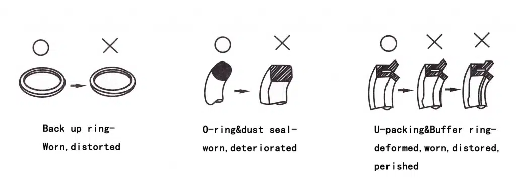
Replace seals every 2000 hours of actual operation.
When bad seal is found, the cause of the damage must be determined and rectified.
When seal is changed, apply grease to seal and seal seat, and hold seal firmly with thumb, index and middle fingers, as per marking.
Be careful not to break seal through excessive deformation.
Wear Inspection
Front cover
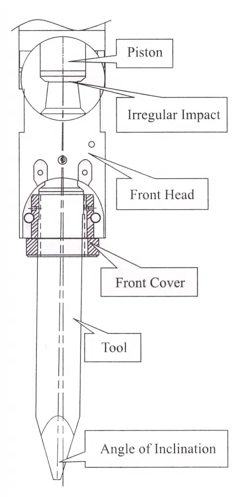
If the clearance between tool and front cover is too big, this could cause of damage, or breakage of tool through piston irregular contact.
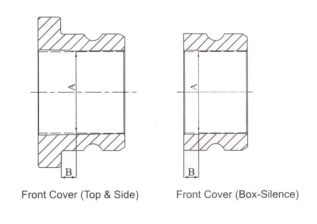
The following table is shown the wear limit of hydraulic breaker tool and front cover for reference purposes.
| Item | Model | Measureat B | Measureat A | RejectInside Dia. |
| 1 | 45 | 10 | 45 | 48 |
| 2 | 53 | 10 | 53 | 56 |
| 3 | 68 | 10 | 68 | 72 |
| 4 | 75 | 10 | 75 | 80 |
| 5 | 85 | 10 | 85 | 85 |
| 6 | 100 | 10 | 100 | 105 |
| 7 | 135 | 10 | 134.5 | 140.5 |
| 8 | 140(A) | 10 | 140(A) | 146 |
| 9 | 150 | 10 | 150 | 156 |
| 10 | 155 | 10 | 155 | 161 |
| 11 | 165(F) | 10 | 165 | 172 |
| 12 | 175 | 10 | 175 | 182 |
If the clearance between tool and front cover is too big, it could cause following problems:
- It could cause irregular impact and this may shorten the life of piston.
- It could cause angle of inclination and this may lead to the breakage of the tool.
Tool Pin
When each tool pin is excessively deformed, it is difficult to replace the tool, therefore, after operating the hydraulic breaker every 100 to 150 hours, change the face of each pin that comes in contact with the tool (The faces of each pin can be used).
When replacing each tool pin, check each part for wear, breakage, scores, etc., especially. And remove burrs and swelling on tool pins.
Replace the tool after grinding the worn parts of front cover and tool pins.
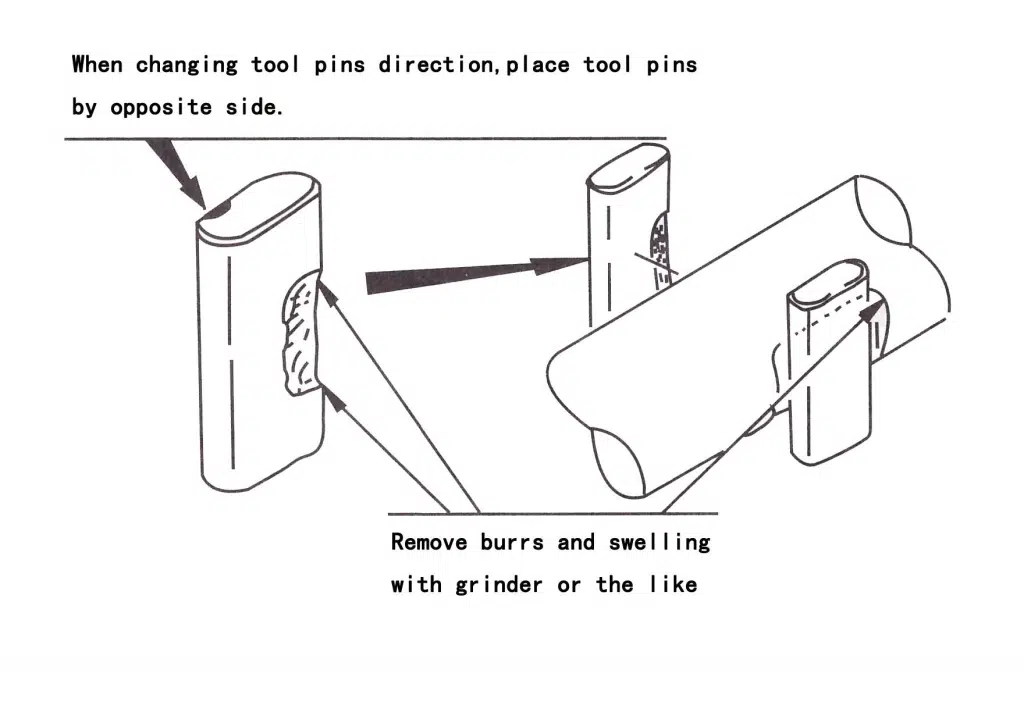
- Change the face of tool pins every 100 to 150 hours of actual operation.
- Replace tool pins every 500 hours of actual operation.
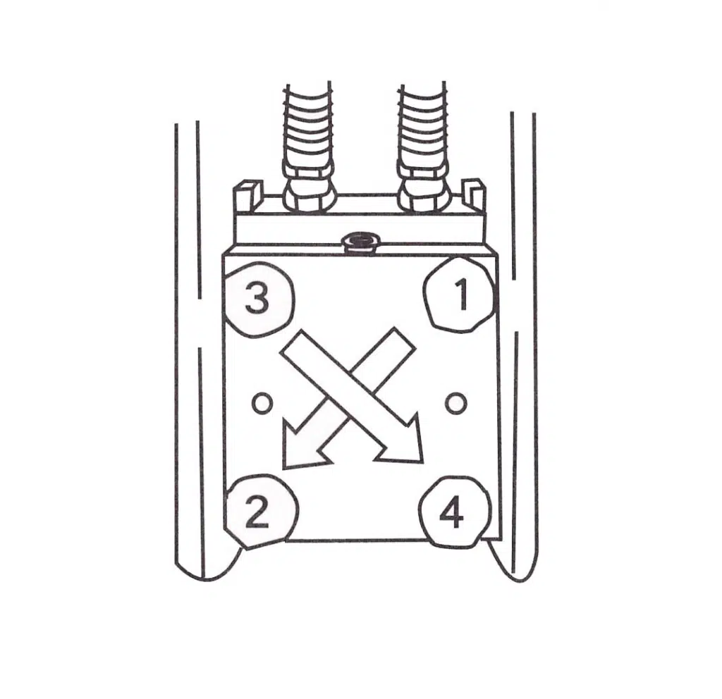
Inspection and Replacement of Through Bolt
Discharge nitrogen (N2) gas in back head complete prior to loosen through bolts.
Remove all through bolts, and inspect for presence of any cracks and damage on through bolts.
When through bolts are assembled, tighten bolts one turn at a time in diagonal sequence; not each nut completely all at once turn of times, not completely at once.
Use to torque wrench of specified range. (Refer to torque table)
Discharge completely N2 gas in back head prior to loosen throughbolts.
Torque Table
Before starting the hydraulic breaker operation, check all kind of bolts and nuts for tightness including the through bolts, socket bolts for accumulator, valve housing socket bolts, valve cover socket bolts and bracket bolts.
Also be sure tighten again any loosen bolts and nuts according to the specified torque.
Using the hydraulic breaker with loose bolts and nuts will cause not only oil leakages but also damages to the screw threads and breakage to the bolts. These can lead also defective operation.
After first 10 hours of operating, retighten the bolts and nuts of all components and sections.
At first, lightly tighten the bolts and nuts by referring to the following torque force.
The bolts and nuts should be screwed down alternately and diagonally until the bolts and nuts are tightened to the uniform torque.
Through Bolt
| Model | Torque(N.M) |
| 45 | 500 |
| 53 | 700 |
| 68 | 1200 |
| 75 | 1300 |
| 85 | 1600 |
| 100 | 2000 |
| 135 | 2700 |
| Model | Torque(N.M) |
| 140(A) | 3200 |
| 150 | 3000 |
| 155 | 3300 |
| 165 | 3300 |
| 165F | 3500 |
| 175 | 3500 |
Bracket Bolt
| Model | Torque(N.M) |
| 45 | 350 |
| 53 | 400 |
| 68 | 1200 |
| 75 | 1200 |
| 85 | 1300 |
| 100 | 2000 |
| 135 | 3000 |
| Model | Torque(N.M) |
| 140(A) | 3000 |
| 150 | 3000 |
| 155 | 3500 |
| 165 | 3500 |
| 165F | 3500 |
| 175 | 4000 |
Socket Bolt – Valve cover
| Model | Torque (N.M) |
| 135 | 440 |
| 150 | 440 |
Socket Bolt – Valve housing
| Model | Torque (N.M) |
| 135 | 440 |
| 150 | 440 |
Socket Bolt – Accumulator cover
| Model | Torque (N.M) |
| 140A | 330 |
| 150 | 330 |
| 155/165 | 330 |
| 165F | 330 |
| 175 | 440 |
Accumulator Body
| Model | Torque (N.M) |
| 140A | 780 |
| 150 | 1565 |
| 155/165 | 440 |
| 165F | 440 |
| 175 | 440 |
Flange Adaptor
| Model | Torque (N.M) |
| 135 | 150 |
| 150 | 150 |
Bolt-Mount cap
| Model | Torque (N.M) |
| 135 | 750 |
| 140/140A | 700 |
| 155 | 1300 |
| 165 | 1300 |
| 175 | 2000 |
Storage
When operation is interrupted or finished
When operation is interrupted or after finished move the base machine on level ground. Remove mud from the hydraulic breaker and set the hydraulic breaker on wood blocks.
- Check whether oil leaks from hydraulic system and whether the tool oil is damaged.
- If the hydraulic breaker is operated in river, dry the hydraulic breaker body and apply the grease to the front head.
Do not touch the tool when hydraulic breaker just stop to work, because it’s very hot.
When hydraulic breaker is not used for a long time-3 weeks or more
- Discharge the nitrogen gas with the back head and accumulator, and then push the piston to avoid rust cylinder.
- Assemble the tool and store the hydraulic breaker indoors after applying the grease to every part, especially internal parts of front head.
If the following procedures are neglected, the rust is generated in the main body to cause serioustroubles.
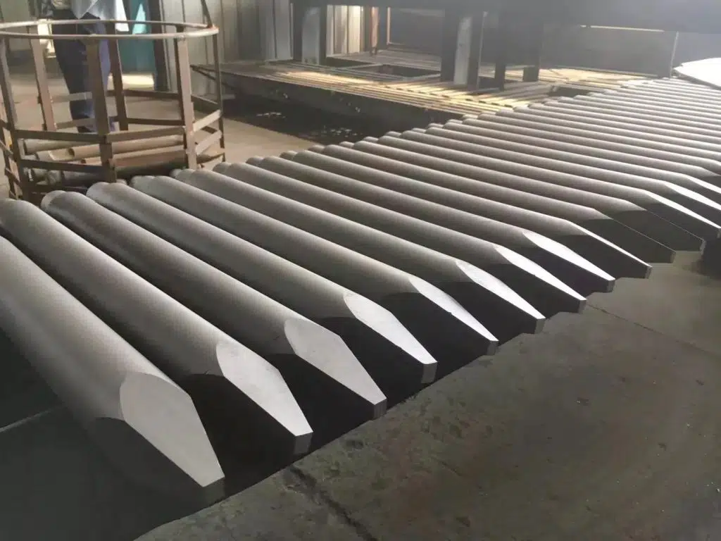
JIANGTU Excavator Break adopts special carbon steel material and heat treatment processes to ensure that the wear of the piston hitting surface is minimized and the service life of the piston is maximized.
Piston production adopts precise tolerance control to ensure that the piston and cylinder can be replaced with a single product, reducing maintenance costs.
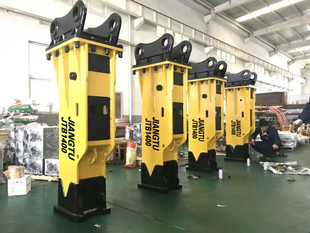
The shell of the breaker has put forward higher and higher requirements for its sealing system. The NOK brand oil seals ensure our hydraulic breaker has low (zero) leakage, low friction and wear, and long service life.
Contact For Our Expert
Find out which attachment & Excavator works best for you!