This trouble-shooting guide has been prepared to aid the operator to locate the problem cause and then remedy when trouble has occurred. If trouble has been caused, obtain details as following checkpoints and contact your local service shop or distributor.
CheckPoint
| Checkpoint (Cause) | Remedy |
| 1. Spool stroke is insufficient. After stop engine, depress the pedal and check if the spool moves full stroke. | Adjust pedal link and control cable joint. |
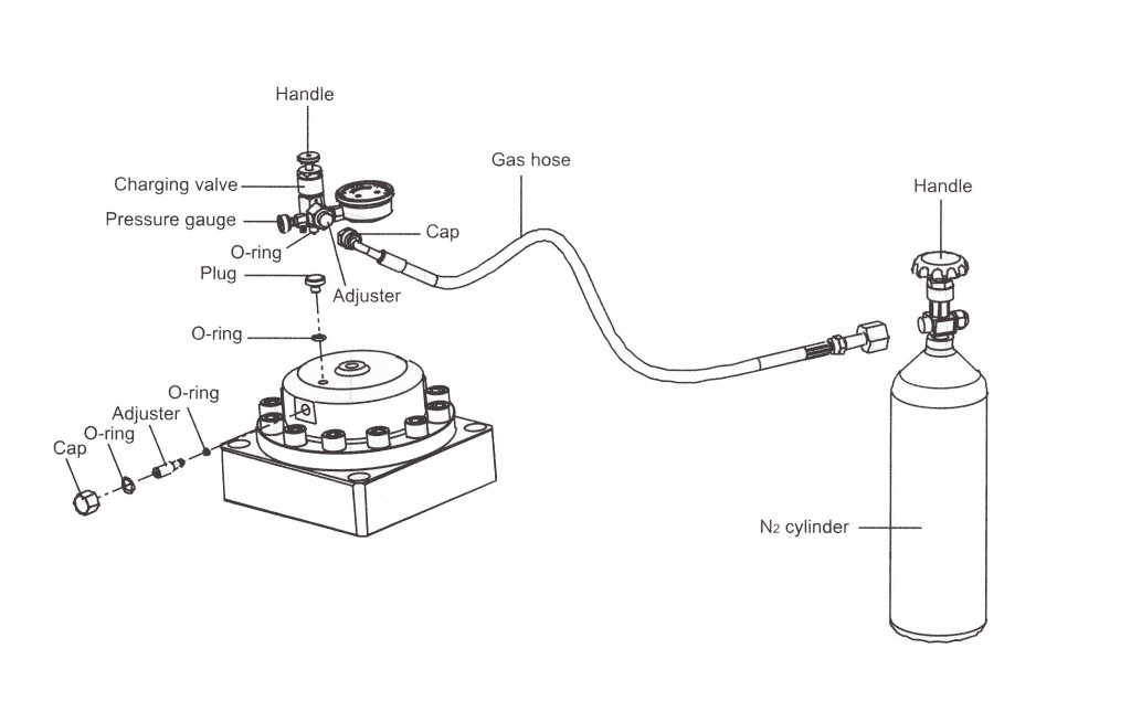
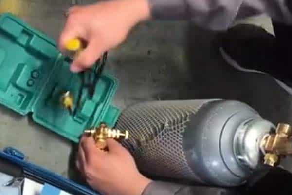
| 2. Hose vibration becomes bigger at hydraulic breaker operation. The high-pressure line oil hose vibrates excessively. (Accumulator gas pressure is lowered)The low-pressure line oil hose vibrates excessively. (Backhead gas pressure is lowered) | Recharge with nitrogen gas or check. Recharge with gas. If the accumulator or back head is recharged but gas leaks at once, the diaphragm or charging valve may be damaged. |
| 3. Piston operates but does not strike the tool. (Tool shank is damaged or seizing) | Pull out the tool and check. If the tool is seizing, repair with a grinder or change the tool and/or tool pins. |
| 4. Hydraulic oil is insufficient. | Refill hydraulic oil. |
| 5. Hydraulic oil is deteriorated or contaminated. Hydraulic oil color change to white or no viscous. (white-colored oil contains air bubbles or water.) | Change all hydraulic oil in the hydraulic system of the base machine. |
| 6. Line filter element is clogged. | Wash or replace the filter element. |
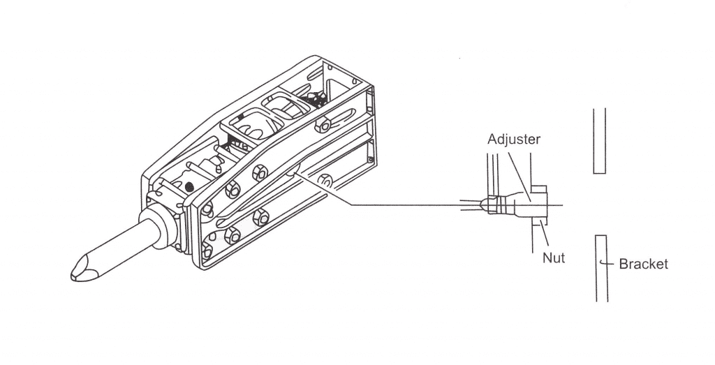
| 7. Impact rate increases excessively. (Breakage or maladjustment of valve adjuster or nitrogen gas leakage from the back head. ) | Adjust or replace the damaged part and check nitrogen gas pressure in the back head. |
| 8. Impact rate decreases excessively. (Backhead gas pressure is excess.) | Adjust nitrogen gas pressure in the backhead. |
| 9. Base machine meander or weak at traveling. (Base machine pump is the defective improper set of main relief pressure.) | Contact base machine service shop. |
Troubleshooting Guide
| Symptom | Cause | Required action |
| No blowout | Excessive nitrogen gas pressure of the back head Stop valve(s) closed Lack of hydraulic oil Wrong pressure adjustment from relief valve Faulty hydraulic hose connection Hydraulic oil in back head infection | Re-adjust nitrogen gas pressure in back head open stop valve Fill hydraulic oil Re-adjust setting pressure Tighten or replace Replace back head o-ring, or seal retainer seals |
| Low impact power | Line leakage or blockage Clogged tank return line filter Lack of hydraulic oil Hydraulic oil contamination, or heat deterioration Poor main pump performance nitrogen gas in back head lower Low flow rate by misadjustment of valve adjuster | Check linesWash filter, or replace Fill hydraulic oil Replace hydraulic oil Contact authorized service shop Refill nitrogen gas Re-adjust valve adjuster Push down tool by excavator operation |
| Irregular impact | Low nitrogen gas pressure in accumulator Bad piston or valve sliding surface Piston moves down/up to blank blow hammer chamber. | Refill nitrogen gas and check the accumulator. Replace diaphragm if need Contact authorized local distributor Push down tool by excavator operation |
| Bad tool movement | Tool diameter incorrect Tool and tool pins would be jammed by tool pins wear Jammed inner bush and tool Deformed tool and piston impact area | Replace tool with genuine parts Smoothen rough surface of tool Smoothen rough surface of inner bush. Replace inner bush if need Replace tool with new |
| Sudden reduction power and pressure line vibration | Gas leakage from the accumulator Diaphragm damage | Replace diaphragm if need |
| Oil leakage from front cover | Cylinder seal worn | Replace seals with new |
| Gas leakage from back head | O-ring and/or gas seal damage | Replace related seals with new |
Guide to tool choice
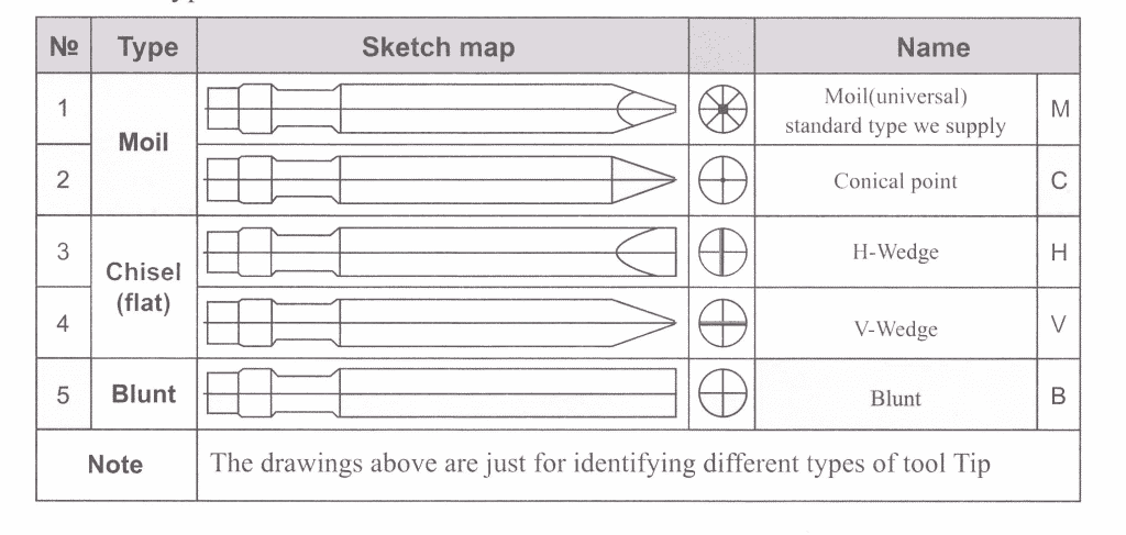
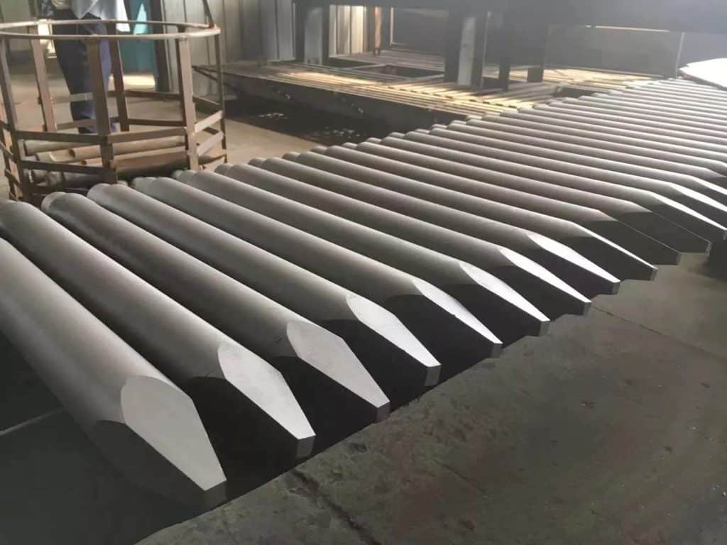
Tool Type
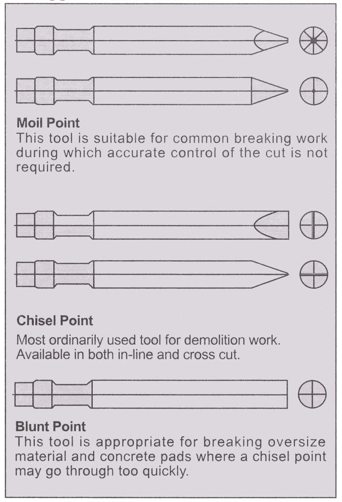
Application Instruction
| NO | Model | Dia(mm) | Length(mm) | Weight(kg) |
| 1 | 45 | 45 | 500 | 8 |
| 2 | 53 | 53 | 580 | 10 |
| 3 | 68 | 68 | 702 | 18 |
| 4 | 75 | 75 | 710 | 22 |
| 5 | 85 | 85 | 745 | 29 |
| 6 | 100 | 100 | 1055 | 57 |
| 7 | 135 | 135 | 1200 | 119 |
| 8 | 140 | 140 | 1300 | 136 |
| 9 | 150 | 150 | 1300 | 160 |
| 10 | 155 | 155 | 1500 | 190 |
| 11 | 165 | 165 | 1500 | 224 |
| 12 | 165F | 165 | 1500 | 224 |
| 13 | 175 | 175 | 1600 | 260 |
Tool claim judgment
Hence, to help users use our products correctly, and ensure long operating life, these claim judgment criteria present defect examples that can occur during use, and the disposition standards applicable in each case.
Breakage of piston impact area or tool pins contact corners
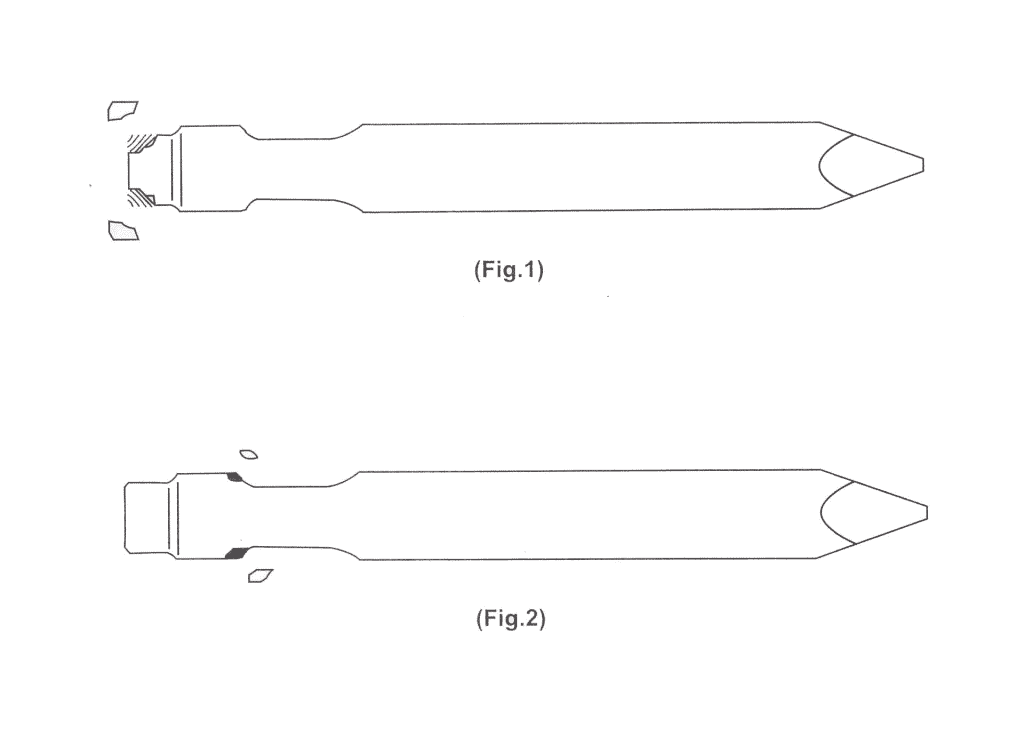
Breakage of piston impacting point or of tool pins contact corners is extremely rare. This phenomenon occurs or when striking force is being concentrated on the tool corners due to unsatisfactory flatness of piston and tool impacting point. If such defect occurs, affected tools may not be accepted under warranty.
Plastic deformation of piston impact area
The possibility of tool tip plastic deformation occurring due to piston is extremely slim. Such defects may occur due to material strength deficiency, or brittleness, resulting from unsatisfactory heat-treatment. If such defect occurs, affected products may be accepted under warranty.
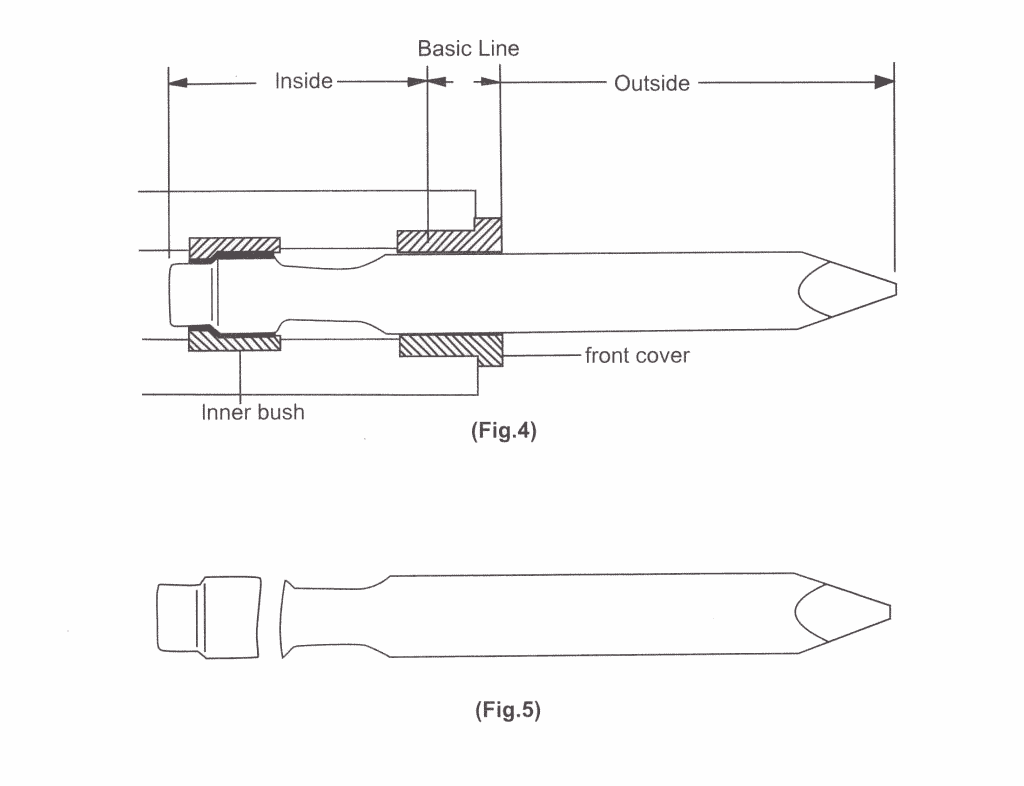
Breaking inside basic line
Should product breakage occur in any direction at a point inside the front cover, as shown in <Fig.5>, from the basic line shown in <Fig.4>, this may be due to defective material, defective heat-treatment; tool deformation, or unsatisfactory shaping of tool neck. Should such defect occur, affected products may be adopted under warranty.
In addition to the causes described above, product breakage inside the basic line may also occur if the interval between the front cover and tool widens due to excessive wear of front cover, coupled with excessive bending load being applied to hydraulic breaker, if any trace of seizure, caused by friction between the front cover and tool, is observed on the surface of the tool body, and if it is clear that product breakage is centered around the area of such seizure, affected products may be rejected under warranty.
Read More: Excavator Attachments Select Guide
Breakage outside basic line
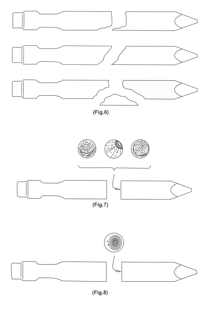
Should product breakage occur at a point outside the front cover, as shown in <Fig.6>, from the basic line shown in <Fig.4>, this may be due to excessive bending load being applied to the tool. Such bending load occurs when, after tool has been inserted into material, the tool is pulled or pushed, or when the tool is struck and pushed when it is not perfectly perpendicular to the surface of the material being worked on.
Fractures, in general, are of the form shown in <Fig.7>. Fatigue breakage, of clamshell form, develops in the areas near breakage start points, caused by stress concentration resulting from bending loads, and then quickly radiates outward, such type of breakage may also occur due to scarring of the tool body during use, as breakage occurring outside the basic line are caused by improper working habits, as
explained above, products incurring such defects shall not be accepted under warranty. However, if a fatigue fracture start point occurs within the tool body, instead of on the surface of tool as shown in <Fig.8>, affected products will be accepted under warranty, as such breakage indicates material defect.
Crushing of tooltip
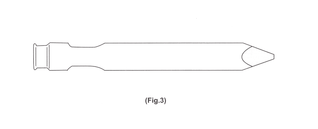
Breaker tools are heat-treated to exhibit high breakage and wear resistance, and defects such as crushing of the tooltip <Fig.9> are not to be expected under normal operating conditions. However, if a tool is hammering continuously for a long period of time without crushing or puncturing the material being worked on, the temperature of the tip rises extremely high, inducing annealing of the heat-treated material, and bringing on plastic deformation(crushing), rather than wear, as explained above, crushing of the tool tip id caused by improper working methods, and, therefore, affected products will be rejected under warranty.
Tool tip wear
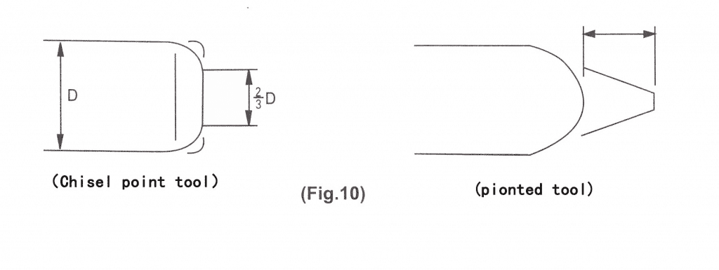
The rates and types of tool tip wear vary with work material and work method. If the diameter of the worn tip of a chisel point tool is less than 2/3 of the tool body diameter, as shown in <Fig.10>; and if the tip of a new pointed tool is worn down in excess of 5mm lengthwise from the tip, this is considered normal tool wear, hence, tools exhibiting such normal wear, as shown in <Fig.10>, will be rejected warranty claim.
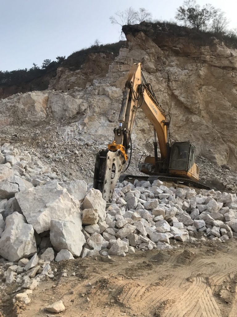
JIANGTU Attachments, as a breaker manufacturer for 12 years. We could provide various types of hydraulic hammer breakers and the chisel selection recommendation and installation instructions for you. If you have any questions, please feel free to contact us.
JIANGTU Excavator Break adopts special carbon steel material and heat treatment processes to ensure that the wear of the piston hitting surface is minimized and the service life of the piston is maximized.
Piston production adopts precise tolerance control to ensure that the piston and cylinder can be replaced with a single product, reducing maintenance costs.
The shell of the breaker has put forward higher and higher requirements for its sealing system. The NOK brand oil seals ensure our hydraulic breaker has low (zero) leakage, low friction and wear, and long service life.
Contact For Our Expert
Find out which attachment & Excavator works best for you!

